


Online-service to create commercial offers
Are you still using MS Word to make your project drawings
and then waste a lot of time calling suppliers
to find the needed equipment and best prices?
Try SecurityProject Zone just now and
absolutely free.
How to start?
It’s very simple.
Step 1. Register in the system.
(Detailed explanation you can find in a “FAQ” section.)
Step 2. After registration you enter Your Account (automatically created). Now you can choose an access level of SecurityProject Zone services according to your requirements.
(Detailed information with regard to the access levels you will find in “PARTNERSHIP” section).
Step 3. Now you can enter “DESIGN” section to create a new project.
[VIDEO GUIDE]
how to create a project of videо surveillance system
[VIDEO GUIDE]
how to create an ELECTRICAL ENGINEERING project
The GUIDEBOOK of ONLINE SECURITY SYSTEMS DESIGN SERVICE
SecurityProject Zone
CONTENT
MENU
TOOLBAR
TOOLBAR STRUCTURE
BUTTON FUNCTIONS
EQUIPMENT CONTROL and SELECTION
Equipment selection using the VIDEO CAMERA as an example
RECOMMENDATIONS on using SecurityProjeсt Zone online service:
Cable run
Cable bending angle of the cable run
Delete function
The Copy / Paste

MENU
For easy online design service SecurityProject Zone navigation, please, use the MENU.
FUNCTIONS DESCRIPTION
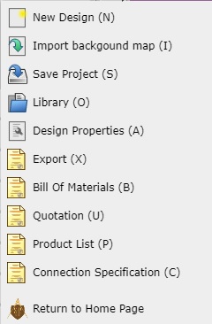
New project
Background import
Save the project
Library
Export
Design Properties
Specification
Commercial offer
Product list
Connections specification
“NEW PROJECT” window (hot key “N”)
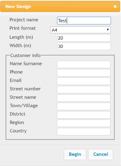
It’s very important for cable lines length calculation.
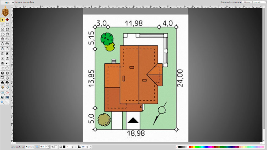
BACKGROUND IMPORT (hot key “I”)
SAVE THE PROJECT (hot key “S”)
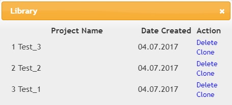
PROJECTS (hot key “O”)
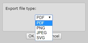
EXPORT (hot key “X”)
PROJECT PROPERTIES (hot key “N”)

PROJECT DOCUMENTS
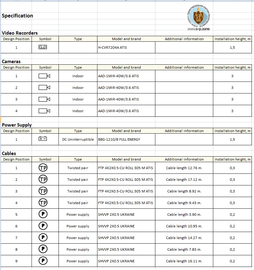
SPECIFICATION (hot key “B”)
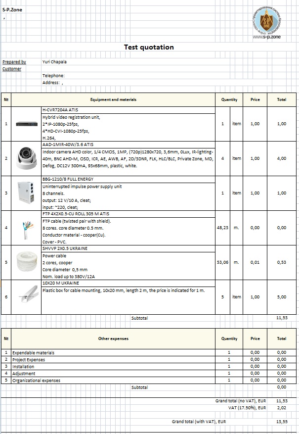
COMMERCIAL OFFER (hot key “U”)
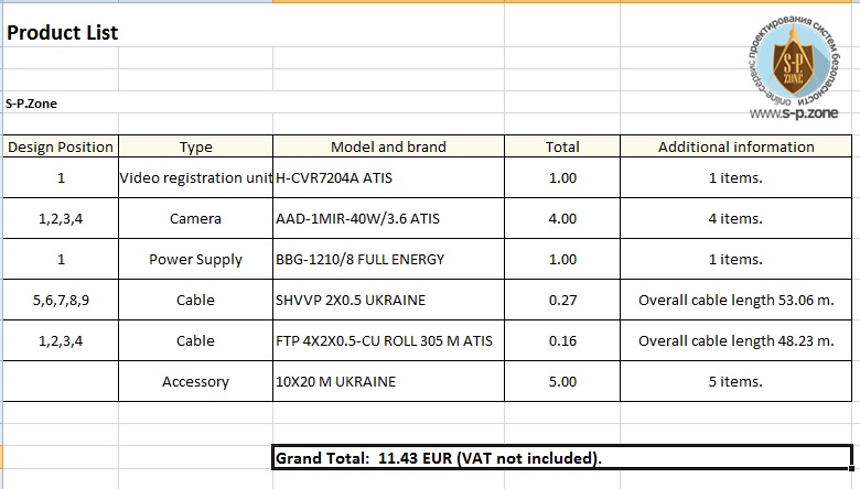
EQUIPMENT LIST (hot key “P”)
CONNECTIONS SPECIFICATION (hot key “C”)
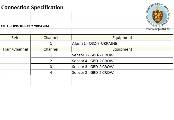
Automatically generated document according to the project plan containing information on connected devices (for example, sensors connected to control input device).
ADDITIONAL OPERATING ELEMENTS

TOOLBAR PANEL
of the SecurityProject Zone design service
Toolbar function is changing and location of the equipment and allows using additional functions and tools for project plan creation.
Toolbar is presented as graphical buttons/pictograms. Press the left click of the mouse to choose a button. While dragging the mouse cursor to the button a text hint about a function of the chosen button pops up.
If the button contains the small triangle in the bottom right corner it means that there is a sub-menu (button) in this category, which will be opened.
Sub-menu is opened by using the long right click of the mouse on the respective button/pictogram.
TOOLBAR BUTTONS FUNCTIONS:
Video surveillance.

internal

external

rotating

video registration unit

camera remote control

transceiver
House intercom

house intercom

house intercom panel
Censor

magnet

infrared (IR)

glass break sensor (GBS)

MW

IR+GBS/MW

infrared barrier

smoke detector

heat detector

handle detector

alarm button

water detector

gas sensor

resistance
Fire/burglar alarm

control and indicating equipment (CIE)

keyboard for CIE

expansion module

message transfer module (GSM completion, radio transmission module etc.)

sound alarm

light alarm

sound-and-light alarm

repeater
Access control

ACS controller

reader

exit button

electromagnetic lock

electromechanical lock

latching device

automatic barrier gate

truncate

door closer
Cable

“C” – coaxial

“TP” – twisted pair

“P” – power cable

“O” – optic cable

“A” – alarm (multiplied) cable

“VGA” – VGA/HDMI
Power supply

DC supply unit

UPS

AC supply unit

UPS AC 220V
Computer equipment

computer

monitor

IP switch

Wi-Fi router

PC connection module
Power panel

power panel

branch box

automatic breaker

starter
Socket

2-pole, opened

double, 2-pole, opened

2-pole, opened, grounding

3-pole, opened, grounding

double,2-pole, hidden

double, 2-pole, hidden

2-pole, hidden, grounding

3-pole, hidden, grounding

2-pole, protected (IP44-IP67)

double, 2-pole, protected (IP44-IP67)

2-pole, grounding, protected (IP44-IP67)

3-pole, grounding, protected (IP44-IP67)
Socket with switch

with 1 switch, opened

with 2 switches, opened

with 3 switches, opened

with 1 switch, hidden

with 2 switches, hidden

with 3 switches, hidden
Special sockets

USB

TV

telephone

Ethernet
Switch

1 pole, opened

double, 1 pole, opened

triple, 1 pole, opened

2 poles, opened

3 poles, opened

1 pole, hidden

double, 1 pole, hidden

triple, 1 pole, hidden

2 poles, hidden

3 poles, hidden

1 pole, protected (IP44-IP67)

2 poles, protected (IP44-IP67)

3 poles, protected (IP44-IP67)
Selector switch

1 pole

2 poles

3 poles

1 pole, protected (IP44-IP67)

2 poles, protected (IP44-IP67)

3 poles, protected (IP44-IP67)

dimmer
Lighting

chandelier

lamp

pointed lamp

wall lamp

searchlight

emergency light

linear lamp

LED strip
Miscellaneous

door bell

warm floor

generator

fan
Line / Curve / Pencil

Line [L]

Curve

Pencil [Q]
Rectangle [R] / Square / “Free-hand” rectangle

Rectangle [R]

Square

“Free-hand” rectangle
Ellipse [E] / Circle / “Free-hand” ellipse

Ellipse [E]

Circle

“Free-hand” ellipse
Text Tool [T]
Image Tool
Zoom Tool [Z]
Indoor images
bath
angle bath
bed
double bed
chair
couch
kitchen
stairs
person sitting
sink
Стол
toilet seat
TV
workspace
Outdoor images
bush
car
person walking
tree
traditional roof
squared roof
round roof
fence
Apartments

room

door

double door

window

arch

gate
ruler
LAYERS
There are few layers for drawing:
1. Priority layer.
2. Video surveillance.
3. Alarm system.
4. Access control.
5. Electricity.
6. Buildings.
7. Drawing.
8. Grid.
9. Background map.
You have to open drop-down menu above the drawing field to layers change, then just make a left mouse button click on the required layers name. Its name will appear in the window beside drop-down menu and it will be marked by color.
When you set the cursor on the layers name in drop-down menu, the objects on the drawing field would be highlighted. The system will automatically put the chosen on the Toolbar object in appropriate layer. Please, pay your attention that the objects from the “Cable”, “Power supply” and “Computer equipment” categories would be put in a current layer, because such equipment could be used in projecting of any system.
There Is a possibility to turn off any layer or all layers in drop-down menu. Just take away a mark beside layers name or take away a mark beside “All”. To restore a layer, please, put the mark beside its name.
1.Priority layer (color red)
This layer has the highest priority. You should use it if you want to put all objects of the project in one layer.
2. Video surveillance (color orange)
The objects from “Video surveillance” and “House intercom” categories are automatically put in this layer.
3. Burglar/Fire alarm (color yellow)
The objects from “Censor” and “Burglar/Fire alarm” categories are automatically put in this layer.
4. Access control (color green)
The objects from “Access control” category are automatically put in this layer.
5. Electricity (color blue)
The objects from “Socket”, “Socket and switch”, “Special socket”, “Switch”, “Selector switch”, “Lighting” and “Miscellaneous” categories are automatically put in this layer.
6. Buildings (color deep blue)
The objects from “Indoor” and “Outdoor” categories are automatically put in this layer.
7. Drawing (color violet)
The objects from “Line/Curve/Pencil”, “Rectangle/Square/‘Free-hand’ rectangle”, “Ellipse/Circle/‘Free-hand’ ellipse”, “Drawing”, “Room” and “Measure line” categories are automatically put in this layer.
CONTROL AND EQUIPMENT SELECTION
You have to choose the equipment pictogram on the Toolbar using the right click of the mouse to locate the equipment on the plan in drawing area.
Drag a pictogram by the pressed right mouse button to move the equipment in the drawing area.
As you install the pictogram on the plan (conditional object identification) EQUIPMENT CHOICE PANEL pops up immediately.
EQUIPMENT CHOICE PANEL.
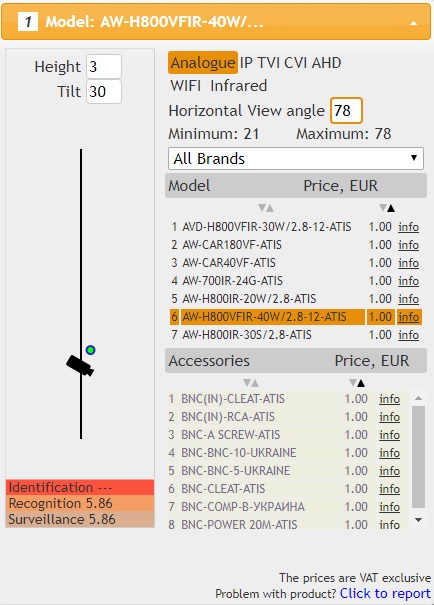 There are following filters on the EQUIPMENT CHOICE PANEL for easy search of the required equipment model:
Device select using the VIDEO CAMERA example
Make a left mouse click on the Toolbar’s “Video camera” pictogram.
In Device Select window select::
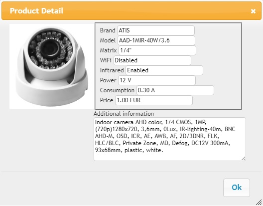
Below would be shown the list of equipment from the Suppliers catalogue which accurately response to required parameters in search filter.
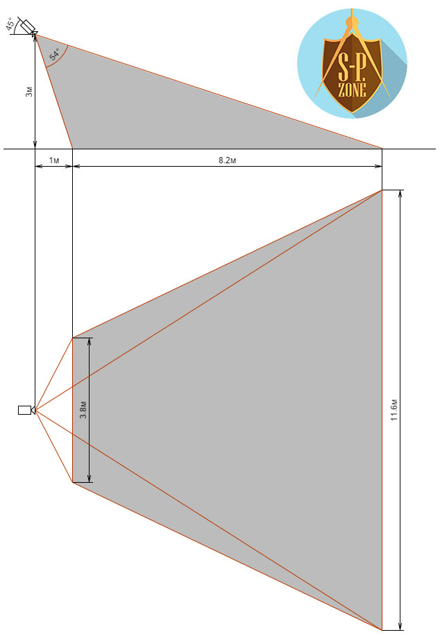
After required device model selection, please, enter the height of video camera installation place and incline angel. The system will automatically calculate and graphically present the video camera observing zone in the project field.
In the left down corner will be shown the data for the distance:
RECOMMENDATIONS on using of SecurityProjet Zone online service
CABLE LAYING
Please, locate in the drawing field two (or more) devices, which it is necessary to connect by cable.
Please, choose from the equipment catalogue the models of such devices, so that the system could make calculations and automatically check the compliance of the devices.
В On the Toolbar choose the Cable pictogram and locate it on the drawing field (clasping the left mouse button on the pictogram on the Toolbar, the system will open a Cable sub-menu). Please, choose required cable from online catalogue.
Connect both cable ends to the devices: clasp the left mouse button on the blue circle (operating element) on the pictogram of the cable end and drag it to the device pictogram.
Please, repeat this procedure for another cable end and another device.
Now the cable is connected to devices and is laid using the shortest route.
CABLE BENDING ANGLE OF THE CABLE RUN
For the cable bending angle change and laying the cable on the required perimeter, point the mouse cursor to cable segment between the device pictogram and cable pictogram. Then clasp the left mouse button on the appeared blue circle and drag it to the required position on the drawing field. An angle of cable run will appear.
The system will automatically calculate the total length of cable run and will show cable length (in meters) over the cable pictogram.
If you need to delete the cable run angle, then click the right mouse button over blue angle circle.
THE COPY/PASTE | DELETE FUNCTIONS
After the object location on the drawing field, there will appear two functional buttons (COPY and DELETE).

If you want to duplicate the object with its preset parameters (for example, model, incline angle, installation height, accessories etc.) just click the COPY icon . The duplicate object will automatically appear on the drawing field.
дFor deleting the object from the project, please, make a left mouse click on DELETE icon over the object’s pictogram. 
When the power supply unit will be connected to device then, depending on cable crossing and length, the working voltage will be shown in comments to video camera. If the voltage from chosen power supply unit would be insufficient to video camera correct working then the device pictogram will “twinkle”.
If you connected a few devices with total power consumption more than chosen power supply unit could produce, the power supply unit pictogram will “twinkle” and in its comments you can see the value of power lack.
The cable could be connected only to devices which support the connection with chosen cable type.
The program partly controls the connection between devices depending on their compliance.
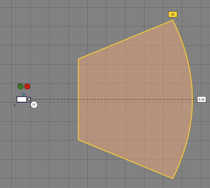
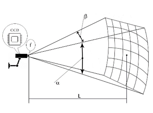
While choosing the video camera, you can see on the plan the camera viewing zone, depending on its type, installation height and incline angle.
The calculation of viewing angles is made according to the formula:
α = 114.5915 * atan (sv / (2 х f))
β = 114.5915 * atan (sg / (2 х f))
. The duplicate object will automatically appear on the drawing field.If you connected a few devices with total power consumption more than chosen power supply unit could produce, the power supply unit pictogram will “twinkle” and in its comments you can see the value of power lack.
The cable could be connected only to devices which support the connection with chosen cable type.
The program partly controls the connection between devices depending on their compliance.
While choosing the video camera, you can see on the plan the camera viewing zone, depending on its type, installation height and incline angle.
β = 114.5915 * atan (sg / (2 х f))
α – vertical viewing angle, β – horizontal viewing angle, f – focus distance, sv and sg – table data
MATRIX ASPECT RATIO 4:3 |
MATRIX ASPECT RATIO 16:9 |
CCD1/4″: sg = 3.39; sv = 2.54;
|
CCD1/4″: sg = 3.69; sv = 2.08;
|

Our support team:
 +380 44 501 4220
 +7 499 404 1116
![]()
Subscribe SecurityProject Zone
SecurityProject Zone social: